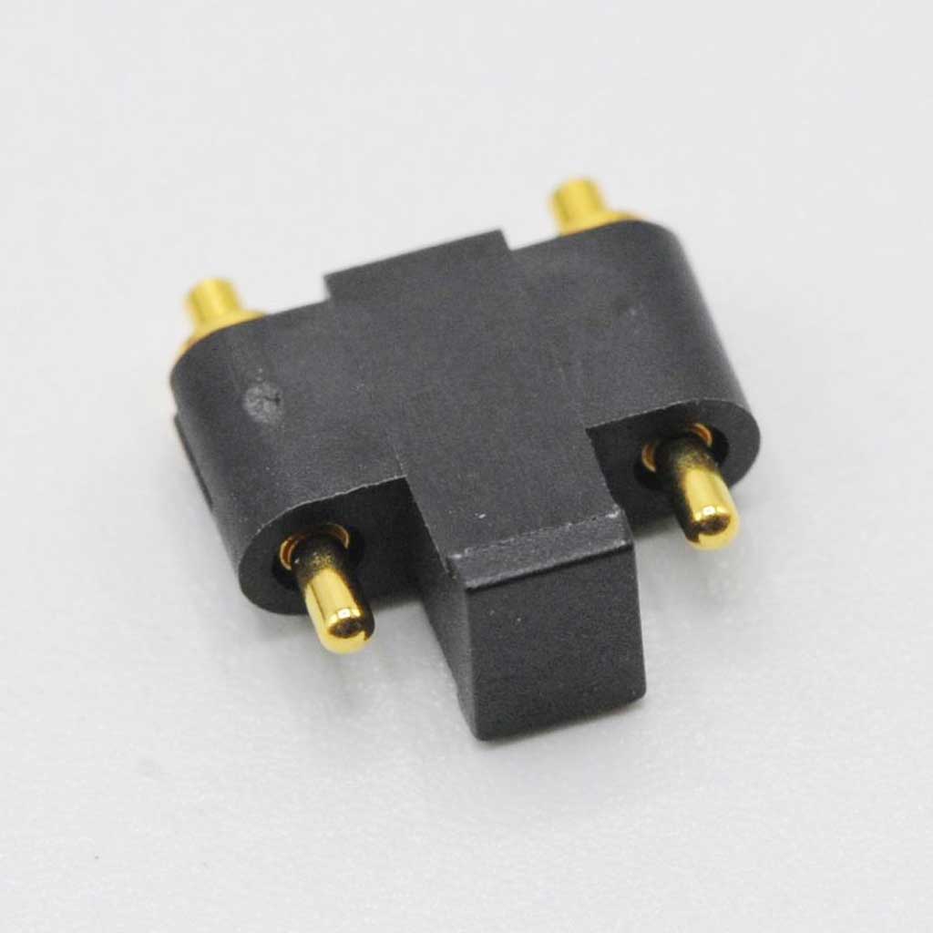
Side connecting type spring pins

Home/ Products /Spring Pin /Side connecting type spring pins
Side connecting type spring pins

Side connecting type spring pins

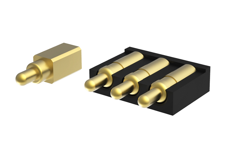
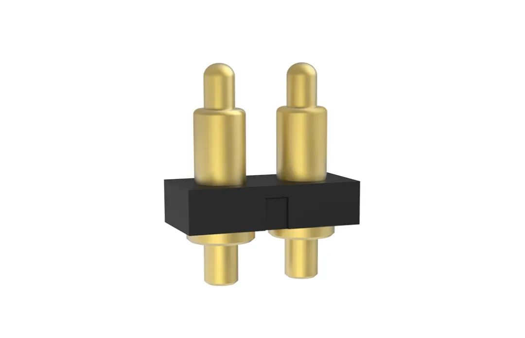
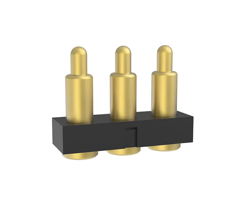
Side connecting type spring pins, which can save installation space, facilitate layout, and can customize multiple pins
  • 接触电阻动态接触电阻通常<30mΩ,低电流电压下稳定传输信号.
  • 电流范围常规0.5-3A,大电流款可达5-100A+,承载力取决于材质、电镀、结构等.
  • 工作温度-40°C至+120°C,部分可扩至更宽温度范围,在极端条件下性能稳定.
  • 耐盐雾性耐盐雾24小时至1000小时+,具体取决于镀层材料和测试标准.
  • 尺寸精度加工精度达μm级,直径精度可达±0.02mm,如高度精度可达±0.05mm,满足严苛要求.
  • 耐久性寿命周期可达数万至百万次压缩,取决于镀层材料和弹簧疲劳特性.

spring pin Characteristics

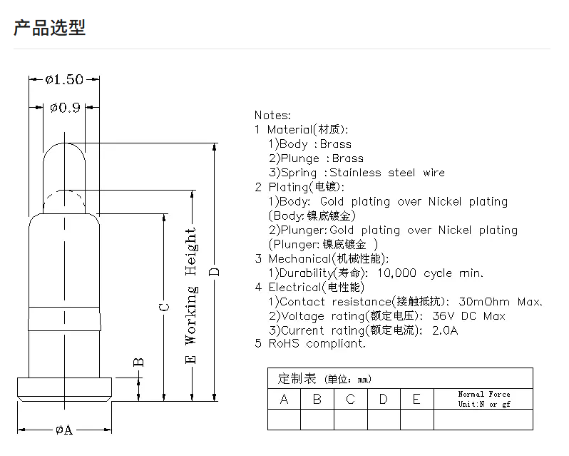
Common structure of spring pin
spring pin
spring pin contact principle
spring pins
Characteristics
  • Long service time, 10,000 times
  • No tooling fee,easy go customize
  • Adjustable and measurable spring force
  • Fine pitch
  • Flexible manufacturing ways: SMT,plug-in...
  • Save space: help mechanical engineer easily allocatecomponents on PCB
  • Good performance on RF solution
  • RoHS and Halogen Free

Common internal structure of spring pin

spring pin type
StructureBall beads structureSloping structurePerforated structureClaw structure
Contact impedance≤ 10mΩ≤ 30mΩ≤ 50mΩ≤ 5mΩ
Long service time10000+10000+10000+500+
Recommended working current10A max10A max10A max10A max
Contact stability★ ★ ★ ★ ☆★ ★ ★ ☆ ☆★ ★ ★ ☆ ☆★ ★ ★ ★ ★
Processing cost★ ★ ★ ☆ ☆★ ★ ☆ ☆ ☆★ ★ ☆ ☆ ☆★ ★ ★ ★ ☆
Main application areasMainly used for charging and condition with certain requirements for vibration and shockMainly used for charging or signal transmission of Consumer electronicsMainly used for signal transmission or grounding antenna,etc.Mainly used high-frequency,anti-instantaneous,the situation which high-reliability is required,such as base stations,military industries,vehicles.
RemarksThe beads increase the internal contacts,the contact is more stable,and the more needle space is requiredThe most commonly used structure on the marketThe space is smaller,but the contact is not stable,the current is easy to run through the spring,and it is not recommended for chargingThe needle and the needle tube have multiple contacts to increase the contact stability

Product Model

side connecting type

IndexPart No.LWHPitchNumber of PositionsCapPositionerL0L1H0Working heightFroce(gf)PDF
1100257-26.34.41.7142NN4.46.10.635.1110+30/-20
21001008-25.21.52.52.542NN3.54.81.253.8150±30gf
3100001-36.34.41.7123NY4.46.10.685.1110+30/-20
4100005-37.73.052.82.53NY3.551.444120 Min
5100609-37.73.052.82.53NN3.55.51.524.5135±25
6100265-37.73.052.82.53NY3.55.51.534.5165±25
7100021-37.72.874.212.53NY3.755.752.154.75130±30
8100514-37.73.052.82.53NN4.056.051.52590±30
9100767-39.74.3522.53NN4.356.0515.3570 Min
10100002-38.61.52.72.83NY3.551.354.2120±25
11100583-38.61.52.72.83NY45.51.354.5130±30
12100289-38.61.52.72.83NY3.55.51.354.7120±25
13100003-38.61.52.72.83NY3.551.355.2120±25
14100574-38.44.41.7533NY4.76.10.725.1140±25
15100778-38.44.41.7533NN4.76.40.725.4120±25
16100557-38.44.41.7533NY4.76.40.725.4120±25
17100290-3954.533NY5.056.5535.55120+30/-20
18100634-3954.533NY5.056.5535.55120+30/-20
19100466-3754.533NY5.056.8535.55130+30/-20
201101024-3954.533NY68.236.2200 Max
21100905-38.61.52.72.83NY343.21.35120±25
22110375-39.21.562.93.13NY3.75.52.14.25175±25
23100073-311.33.544.23NY5.57.31.56.3100 Min
24100001-48.34.41.7124NN4.46.10.685.1110+30/-20
25100049-48.34.41.7124NN4.96.60.685.6110+30/-20
26100760-4104.41.72.54NY4.46.10.725.380 Min
27100594-4104.41.72.54NY4.46.10.725.4100 Min
28100637-4104.41.72.54NN4.46.10.725.4100 Min
29100542-4104.41.72.54NY4.46.10.725.4100 Min
30100328-410.556.62.54NY5.27.25.16.2120+30/-20
31100685-413.824.742.54NY5.157.1526.35115±25
32100385-410.556.62.54NY5.57.85.16.6120+30/-20
33100938-517.56.3735NN6.78.257.2150±35
34100814-512.54.41.82.55NN4.46.10.725.380gf min
351001033-818.53.92.728NY4.35.61.354.990±20
36110414-817.25.53.128NY67.81.556.850±25
37100722-617.459.82.26NN5.46.985.9120±25
38101010219606.34.41.7142NN5.16.60.684.8110±30

spring pin Characteristics

Common structure of spring pin
spring pin
spring pin contact principle
spring pins
Characteristics
  • Long service time, 10,000 times
  • No tooling fee,easy go customize
  • Adjustable and measurable spring force
  • Fine pitch
  • Flexible manufacturing ways: SMT,plug-in...
  • Save space: help mechanical engineer easily allocatecomponents on PCB
  • Good performance on RF solution
  • RoHS and Halogen Free

Common internal structure of spring pin

spring pin type
StructureBall beads structureSloping structurePerforated structureClaw structure
Contact impedance≤ 10mΩ≤ 30mΩ≤ 50mΩ≤ 5mΩ
Long service time10000+10000+10000+500+
Recommended working current10A max10A max10A max10A max
Contact stability★ ★ ★ ★ ☆★ ★ ★ ☆ ☆★ ★ ★ ☆ ☆★ ★ ★ ★ ★
Processing cost★ ★ ★ ☆ ☆★ ★ ☆ ☆ ☆★ ★ ☆ ☆ ☆★ ★ ★ ★ ☆
Main application areasMainly used for charging and condition with certain requirements for vibration and shockMainly used for charging or signal transmission of Consumer electronicsMainly used for signal transmission or grounding antenna,etc.Mainly used high-frequency,anti-instantaneous,the situation which high-reliability is required,such as base stations,military industries,vehicles.
RemarksThe beads increase the internal contacts,the contact is more stable,and the more needle space is requiredThe most commonly used structure on the marketThe space is smaller,but the contact is not stable,the current is easy to run through the spring,and it is not recommended for chargingThe needle and the needle tube have multiple contacts to increase the contact stability

Product Model

side connecting type

IndexPart No.LWHPitchNumber of PositionsCapPositionerL0L1H0Working heightFroce(gf)PDF
1100257-26.34.41.7142NN4.46.10.635.1110+30/-20
21001008-25.21.52.52.542NN3.54.81.253.8150±30gf
3100001-36.34.41.7123NY4.46.10.685.1110+30/-20
4100005-37.73.052.82.53NY3.551.444120 Min
5100609-37.73.052.82.53NN3.55.51.524.5135±25
6100265-37.73.052.82.53NY3.55.51.534.5165±25
7100021-37.72.874.212.53NY3.755.752.154.75130±30
8100514-37.73.052.82.53NN4.056.051.52590±30
9100767-39.74.3522.53NN4.356.0515.3570 Min
10100002-38.61.52.72.83NY3.551.354.2120±25
11100583-38.61.52.72.83NY45.51.354.5130±30
12100289-38.61.52.72.83NY3.55.51.354.7120±25
13100003-38.61.52.72.83NY3.551.355.2120±25
14100574-38.44.41.7533NY4.76.10.725.1140±25
15100778-38.44.41.7533NN4.76.40.725.4120±25
16100557-38.44.41.7533NY4.76.40.725.4120±25
17100290-3954.533NY5.056.5535.55120+30/-20
18100634-3954.533NY5.056.5535.55120+30/-20
19100466-3754.533NY5.056.8535.55130+30/-20
201101024-3954.533NY68.236.2200 Max
21100905-38.61.52.72.83NY343.21.35120±25
22110375-39.21.562.93.13NY3.75.52.14.25175±25
23100073-311.33.544.23NY5.57.31.56.3100 Min
24100001-48.34.41.7124NN4.46.10.685.1110+30/-20
25100049-48.34.41.7124NN4.96.60.685.6110+30/-20
26100760-4104.41.72.54NY4.46.10.725.380 Min
27100594-4104.41.72.54NY4.46.10.725.4100 Min
28100637-4104.41.72.54NN4.46.10.725.4100 Min
29100542-4104.41.72.54NY4.46.10.725.4100 Min
30100328-410.556.62.54NY5.27.25.16.2120+30/-20
31100685-413.824.742.54NY5.157.1526.35115±25
32100385-410.556.62.54NY5.57.85.16.6120+30/-20
33100938-517.56.3735NN6.78.257.2150±35
34100814-512.54.41.82.55NN4.46.10.725.380gf min
351001033-818.53.92.728NY4.35.61.354.990±20
36110414-817.25.53.128NY67.81.556.850±25
37100722-617.459.82.26NN5.46.985.9120±25
38101010219606.34.41.7142NN5.16.60.684.8110±30
Side connecting type spring pins
P/N 长 L 宽 W 高 H 间距 Pitch 盖子 Cap 定位柱 Positioner A B C D 工作高度Working height 弹力 Froce(gf) Actions
100257-2 6.3 4.4 1.71 4 N N 5.1 110+30/-20
1001008-2 5.2 1.5 2.5 2.54 N N 3.8 150±30gf
100001-3 6.3 4.4 1.71 2 N Y 5.1 110+30/-20
100005-3 7.7 3.05 2.8 2.5 N Y 4 120 Min
100609-3 7.7 3.05 2.8 2.5 N N 4.5 135±25
100265-3 7.7 3.05 2.8 2.5 N Y 4.5 165±25
100021-3 7.7 2.87 4.21 2.5 N Y 4.75 130±30
100514-3 7.7 3.05 2.8 2.5 N N 5 90±30
100767-3 9.7 4.35 2 2.5 N N 5.35 70 Min
100002-3 8.6 1.5 2.7 2.8 N Y 4.2 120±25
100583-3 8.6 1.5 2.7 2.8 N Y 4.5 130±30
100289-3 8.6 1.5 2.7 2.8 N Y 4.7 120±25
100003-3 8.6 1.5 2.7 2.8 N Y 5.2 120±25
100574-3 8.4 4.4 1.75 3 N Y 5.1 140±25
100778-3 8.4 4.4 1.75 3 N N 5.4 120±25
100557-3 8.4 4.4 1.75 3 N Y 5.4 120±25
100290-3 9 5 4.5 3 N Y 5.55 120+30/-20
100634-3 9 5 4.5 3 N Y 5.55 120+30/-20
100466-3 7 5 4.5 3 N Y 5.55 130+30/-20
1101024-3 9 5 4.5 3 N Y 6.2 200 Max
100905-3 8.6 1.5 2.7 2.8 N Y 1.35 120±25
110375-3 9.2 1.56 2.9 3.1 N Y 4.25 175±25
100073-3 11.3 3.5 4 4.2 N Y 6.3 100 Min
100001-4 8.3 4.4 1.71 2 N N 5.1 110+30/-20
100049-4 8.3 4.4 1.71 2 N N 5.6 110+30/-20
100760-4 10 4.4 1.7 2.5 N Y 5.3 80 Min
100594-4 10 4.4 1.7 2.5 N Y 5.4 100 Min
100637-4 10 4.4 1.7 2.5 N N 5.4 100 Min
100542-4 10 4.4 1.7 2.5 N Y 5.4 100 Min
100328-4 10.5 5 6.6 2.5 N Y 6.2 120+30/-20
100685-4 13.82 4.7 4 2.5 N Y 6.35 115±25
100385-4 10.5 5 6.6 2.5 N Y 6.6 120+30/-20
100938-5 17.5 6.3 7 3 N N 7.2 150±35
100814-5 12.5 4.4 1.8 2.5 N N 5.3 80gf min
1001033-8 18.5 3.9 2.7 2 N Y 4.9 90±20
110414-8 17.2 5.5 3.1 2 N Y 6.8 50±25
100722-6 17.4 5 9.8 2.2 N N 5.9 120±25
What key factors should be considered when selecting a spring pin connector?
1. Application: current rating (high-current designs often need a beveled tip + ball structure), signal integrity (low-impedance design), and operating environment (temperature / dust resistance, etc.);
2. Structure: flat-bottom tips are more prone to poor contact; a beveled / cut-face design is preferred for stable side thrust and lower impedance. For high current (e.g. 30A+), reduce the current load carried by the spring;
3. Plating: gold plating (3–20 μ") improves conductivity; nickel plating (50–100 μ") improves oxidation resistance. High-current applications usually need thicker plating;
4. Working stroke and spring force: too short a stroke can over-compress and damage the spring; too long a stroke can cause poor contact. Excess force increases wear; too little force reduces contact stability;
5. If the requirements are not fully defined, contact us at a-black@foxmail.com for technical support.
Does Tanben Electronics provide stamped and formed parts?
1. Yes. Tanben Electronics has a full set of stamping and turned-part manufacturing equipment, plus mature process capability;
2. Stamped parts offer more stable dimensions and are suitable for high-precision requirements.
Are the connectors sealed / waterproof?
1. Waterproof versions are available, including IP67-rated designs (special design required).
How can poor contact / unstable conduction be avoided?
1. Calculate the spring compression stroke accurately during design to keep contact pressure in the proper range;
2. Strengthen cleaning in production to avoid solder, oil, and other contamination; maintain and remove debris during use;
3. Use wear-resistant, oxidation-resistant plating (e.g. gold) and avoid long-term use in highly corrosive environments;
4. Control structural tolerances strictly so the plunger, barrel, and pad alignment stay accurate.
What is the root cause of premature failure in spring-loaded connectors?
1. Pin sticking or oxidation caused by side force or contamination (keep the contact surfaces clean).
How can spring fatigue or breakage be avoided?
1. Select a spring pin life rating that matches the mating-cycle frequency and do not exceed the rated cycles;
2. Avoid keeping the spring at full compression for long periods; reserve a reasonable stroke margin.
How can plunger or barrel deformation be avoided?
1. Avoid impact and uneven force during installation; control SMT reflow temperature to prevent base softening;
2. Use higher-strength materials (e.g. stainless-steel plunger, metal barrel).
How can base detachment or poor soldering be avoided?
1. Optimize pad design (increase pad area) and control reflow temperature and time;
2. When needed, add adhesive for secondary fixation to improve vibration resistance.
How can performance degradation in high-temperature environments be avoided?
1. Use high-temperature base materials (e.g. ceramic or high-temp plastics);
2. Do not operate beyond the specified temperature range; add thermal design when necessary.
How can short circuits caused by humid or corrosive environments be avoided?
1. Add sealing structures (e.g. gaskets/O-rings) to block moisture and corrosive media;
2. Use corrosion-resistant plating and materials, and inspect protection performance regularly.
How can displacement caused by vibration or shock be avoided?
1. Use soldering plus adhesive dual fixation to improve mounting strength;
2. Avoid equipment vibration frequencies in the design, or add damping structures.
How can improper SMT reflow temperature control be avoided?
1. Follow the spring pin soldering temperature specification and monitor the reflow profile with a temperature profiler;
2. Prefer SMT models with better temperature resistance when possible.
How can pad misalignment be avoided?
1. Ensure PCB pad pitch matches the spring pin lead pitch during design;
2. Improve placement accuracy and check alignment before soldering.
How should the connectors be cleaned correctly during use?
1. Use neutral cleaners; avoid strong corrosive solvents and overly long ultrasonic cleaning;
2. Dry promptly after cleaning to minimize plating contact time with the cleaner.
How can current / voltage overload be avoided?
1. Select spring pins whose rated current and voltage match the actual working load;
2. Do not operate beyond the electrical specification; add overload protection when needed.
How can high-frequency signal loss be reduced?
1. For high-frequency applications, choose models with low parasitic inductance/capacitance and optimize the structure to reduce interference;
2. Perform impedance matching tests to ensure signal transmission quality.
How can mating cycles be increased?
1. According to the device mating frequency, choose high-life spring pins (e.g. gold-plated springs and reinforced mechanical design).
How can internal foreign-object jamming be prevented?
1. Enforce strict 5S control in production to avoid metal chips and solder residue;
2. Add dust-proof / waterproof sealing to block external particles.
What is the easiest way to search for products on this website?
1. Filter by model, dimensions, and drawings;
2. Or contact technical support at a-black@foxmail.com.