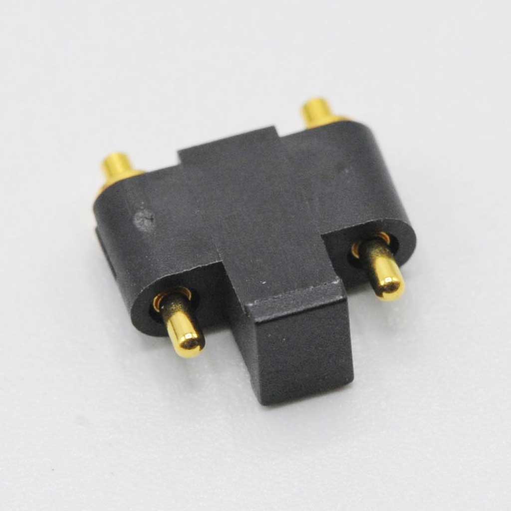
3Pin平底式Spring Pin Connector |贴片式弹簧针连接器| 防腐蚀、低阻抗 | 支持定制

Home/ Products /Spring Pin /3Pin平底式Spring Pin Connector |贴片式弹簧针连接器| 防腐蚀、低阻抗 | 支持定制
3Pin平底式Spring Pin Connector |贴片式弹簧针连接器| 防腐蚀、低阻抗 | 支持定制

3Pin平底式Spring Pin Connector |贴片式弹簧针连接器| 防腐蚀、低阻抗 | 支持定制

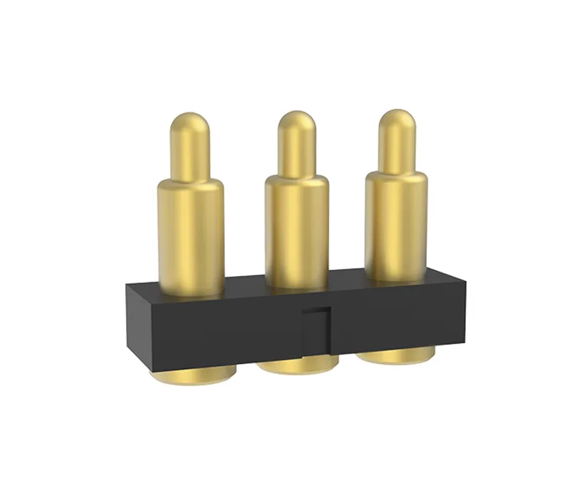
3Pin平底式Spring Pin Connector |贴片式弹簧针连接器| 防腐蚀、低阻抗 | 支持定制 平底式 3Pin Spring Pin Connector,专注解决微型设备连接痛点,平底结构减少安装空间,镀金触点提升耐磨性,低阻抗特性适配高频信号传输,适用于医疗、消费电子、汽车电子领域。
  • Contact ResistanceDynamic contact resistance typically <30 mΩ for stable low-current signal transmission.
  • Current RangeTypically 0.5-3A; high-current variants up to 5-100A+, depending on material, plating and structure.
  • Operating Temperature-40°C to +120°C, partially extendable to a wider range with stable extreme-condition performance.
  • Salt Spray ResistanceSalt-spray resistance from 24 h to 1000 h+, depending on plating material and test standard.
  • Dimensional AccuracyMicron-level machining; diameter tolerance to ±0.02mm and height tolerance to ±0.05mm for demanding requirements.
  • DurabilityService life from tens of thousands to millions of compressions, depending on plating and spring fatigue.

3Pin Spring Pin Connector

Contact Resistance
Dynamic contact resistance typically <30 mΩ for stable low-current signal transmission.
Current Range
Typically 0.5-3A; high-current variants up to 5-100A+, depending on material, plating and structure.
Operating Temperature
-40°C to +120°C, partially extendable to a wider range with stable extreme-condition performance.
Salt Spray Resistance
Salt-spray resistance from 24 h to 1000 h+, depending on plating material and test standard.
Dimensional Accuracy
Micron-level machining; diameter tolerance to ±0.02mm and height tolerance to ±0.05mm for demanding requirements.
Durability
Service life from tens of thousands to millions of compressions, depending on plating and spring fatigue.

Overview

3Pin Spring Pin Connector from Tanben Electronics features low contact resistance, stable current carrying and customizable pin count / pitch / mounting options for consumer electronics, industrial control and communication devices.

Technical Specifications

Contact ResistanceDynamic contact resistance typically <30 mΩ for stable low-current signal transmission.
Current RangeTypically 0.5-3A; high-current variants up to 5-100A+, depending on material, plating and structure.
Operating Temperature-40°C to +120°C, partially extendable to a wider range with stable extreme-condition performance.
Salt Spray ResistanceSalt-spray resistance from 24 h to 1000 h+, depending on plating material and test standard.
Dimensional AccuracyMicron-level machining; diameter tolerance to ±0.02mm and height tolerance to ±0.05mm for demanding requirements.
DurabilityService life from tens of thousands to millions of compressions, depending on plating and spring fatigue.

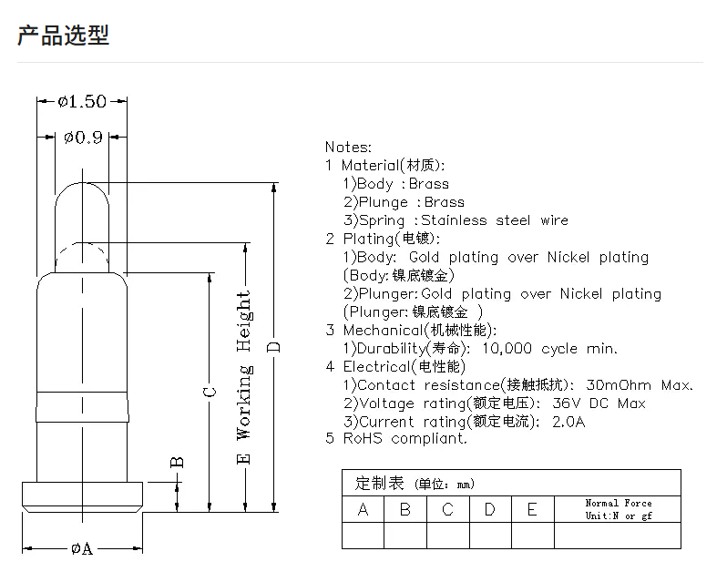
Drawings

3Pin Spring Pin Connector

3Pin Spring Pin Connector

AIserver high-speed interconnect solution

robot precision interconnect solution

chip-test high-frequency solution

3 Pinflat-bottomspring pin connector

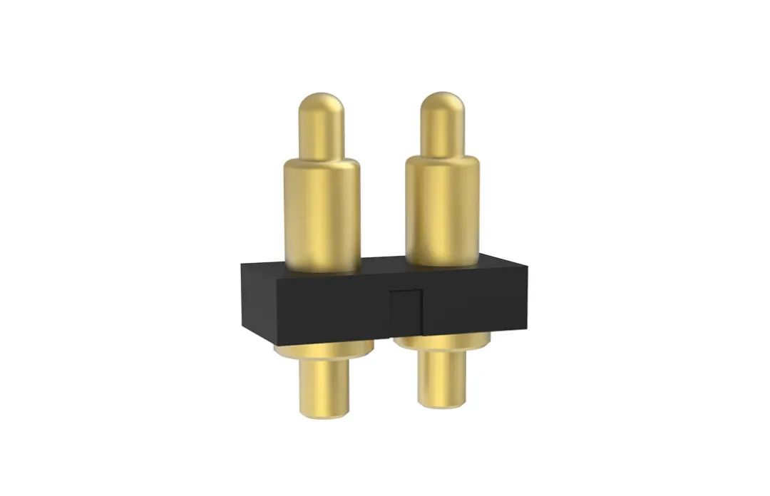
2 PINthrough-hole / DIPspring pin connector

side-contactspring pin connector

3Pin平底式Spring Pin Connector |贴片式弹簧针连接器| 防腐蚀、低阻抗 | 支持定制
P/N 长 L 宽 W 高 H 间距 Pitch 盖子 Cap 定位柱 Positioner A B C D 工作高度Working height 弹力 Froce(gf) Actions
100351-3 7.6 2.5 1.5 2.54 Y N 1.6 0.4 2.2 3 2.5 90 Min
100172-3 7.6 2.5 1.5 2.54 Y N 1.65 0.6 2.4 3.2 2.7 70 Min
100282-3 7.6 2.5 1.5 2.54 Y N 2 0.4 2.5 3.5 2.9 100±30
100145-3 7.6 2.5 1.5 2.54 Y N 2 0.4 2.7 3.8 3.1 80±30
100424-3 7.6 2.5 1.5 2.54 Y N 2 0.5 3 4 3.2 140±30
110341-3 7.6 2.5 1.5 2.54 N N 1.9 0.9 2.9 4.2 3.3 100 Min
100189-3 7.6 2.5 1.5 2.54 Y N 2 0.5 3 4.3 3.35 90 Min
100324-3 7.6 2.5 1.5 2.54 Y N 2 0.5 3.3 4.6 3.8 80+60/-20
100130-3 7.6 2.5 1.5 2.54 Y N 2 0.5 3.5 5 3.8 60±15
100226-3 7.6 2.5 1.5 2.54 Y N 2 0.5 3.5 4.8 3.8 80 Min
100085-3 7.6 2.5 1.5 2.54 Y N 2 0.5 3 4.5 3.9 80±20
100782-3 7.6 2.5 1.5 2.54 Y N 2 0.5 3.5 5 4 35±15
100453-3 7.6 2.5 1.5 2.54 Y N 2 0.5 3.5 5 4.2 80±20
100130-3 7.6 2.5 1.5 2.54 Y N 2 0.5 3.5 5 4.2 45±10
100176-3 7.6 2.5 1.5 2.54 Y N 2 0.5 4 5.5 4.5 125±30
100773-3 7.6 2.5 1.5 2.54 Y N 2 0.5 4 5.5 4.5 35±15
100774-3 7.6 2.5 1.5 2.54 Y N 2 0.5 4 5.5 4.5 75±25
1001101-3 7.6 2.5 1.5 2.54 Y N 2 0.5 4 6 5 80 Min
100635-3 7.6 2.5 1.5 2.54 Y N 2 0.5 4.5 6 5 90 Min
110867-3 10.5 2.5 1.5 2.54 N N 2 0.5 4.5 6.3 5.1 95 Min
100632-3 7.6 2.5 1.5 2.54 Y N 2 0.5 4 6 5.2 65±20
10101031148 7.6 2.5 1.5 2.54 Y N 1.8 1.3 4.5 6.8 5.5 90 Min
100204-3 7.6 2.5 1.5 2.54 Y N 2 1 5 7 5.5 157±30
110734-3 7.6 2.5 1.5 2.54 N N 2 1 5.5 7.5 5.9 80±25
110866-3 7.6 2.5 1.5 2.54 N N 2 0.5 5.2 7 6.2 90 Min
110317-3 7.6 2.5 1.5 2.54 N N 2 1 5.5 7.5 6.5 80 Min
110736-3 7.6 2.5 1.5 2.54 N N 2 1 5 7.3 6.5 90±20
110406-3 7.6 2.5 1.5 2.54 N N 2 1.6 7.2 9 8 100±30
100255-3 8.5 2.5 1.5 3 Y N 2 0.4 2.2 3 2.5 90 Min
100699-3 8.5 2.5 1.5 3 Y N 2 0.4 2.5 3.5 2.9 100±30
100110-3 8.5 2.5 1.5 3 Y N 2 0.5 3 4.3 3.5 120±25
100430-3 8.5 2.5 1.5 3 Y N 2 0.5 3 4.5 3.6 180 Max
100234-3 8.5 2.5 1.5 3 Y N 2 0.5 3.5 4.8 3.8 80 Min
100418-3 8.5 2.5 1.5 3 Y N 2 0.5 3.5 5 4 150±30
100521-3 8.5 2.5 1.5 3 Y N 2 0.5 4 5.5 4.5 30±15
100147-3 8.5 2.5 1.5 3 Y N 2 0.5 4 5.5 4.5 65±25
100601-3 8.5 2.5 1.5 3 Y N 2 0.5 4 5.5 4.5 30±10
100712-3 8.5 2.5 1.5 3 Y N 2 0.5 4 5.8 4.8 90 Min
110227-3 8.5 2.5 1.5 3 N N 2 1 5 6.5 5.5 125±30
100546-3 8.5 2.5 1.5 3 Y N 2 1 5 7 6 115±30
110368-3 8.5 2.5 1.5 3 N N 2 1.5 6 7.6 6.6 100±30
110672-3 8.5 2.5 1.5 3 N N 2 1.5 6 8.5 7 140±25
110530-3 8.5 2.5 1.5 3 N N 2 1.8 7.2 10 9 100±25
110755-3 10.5 2.5 1.5 4 N N 2 1.6 7.2 9 8 100±30
100867-3 10.5 2.5 1.5 4 Y N 2 0.5 4.5 6.3 5.1 90 Min
10101031350 10.5 2.5 1.5 4 Y N 2 0.5 3.2 4.5 3.6 80 min
10101031317 10.5 2.5 1.5 4 Y N 2 1.9 6.5 8.5 7.15 168±30
110713-3 12.76 2.5 2 5.08 N N 2 1.6 7.2 9 8 100±30
110667-3 17.78 2.54 2.4 7.62 N N 2 0.5 3 4 3.2 140±35
10101031724 12.5 2.5 1.8 4.3 Y Y 1.8 0.3 2.1 2.9 2.3 70±20
10101031226 7.6 2.5 1.5 2.54 Y N 2 0.5 4 6 5 80 min
10101031271 7.6 2.5 1.5 2.54 Y Y 2 0.5 5 6.5 5.5 90 min
100736-3 7.6 2.5 1.5 2.54 Y N 2 1 5 7.3 6.5 90±25
What key factors should be considered when selecting a spring pin connector?
1. Application: current rating (high-current designs often need a beveled tip + ball structure), signal integrity (low-impedance design), and operating environment (temperature / dust resistance, etc.);
2. Structure: flat-bottom tips are more prone to poor contact; a beveled / cut-face design is preferred for stable side thrust and lower impedance. For high current (e.g. 30A+), reduce the current load carried by the spring;
3. Plating: gold plating (3–20 μ") improves conductivity; nickel plating (50–100 μ") improves oxidation resistance. High-current applications usually need thicker plating;
4. Working stroke and spring force: too short a stroke can over-compress and damage the spring; too long a stroke can cause poor contact. Excess force increases wear; too little force reduces contact stability;
5. If the requirements are not fully defined, contact us at a-black@foxmail.com for technical support.
Does Tanben Electronics provide stamped and formed parts?
1. Yes. Tanben Electronics has a full set of stamping and turned-part manufacturing equipment, plus mature process capability;
2. Stamped parts offer more stable dimensions and are suitable for high-precision requirements.
Are the connectors sealed / waterproof?
1. Waterproof versions are available, including IP67-rated designs (special design required).
How can poor contact / unstable conduction be avoided?
1. Calculate the spring compression stroke accurately during design to keep contact pressure in the proper range;
2. Strengthen cleaning in production to avoid solder, oil, and other contamination; maintain and remove debris during use;
3. Use wear-resistant, oxidation-resistant plating (e.g. gold) and avoid long-term use in highly corrosive environments;
4. Control structural tolerances strictly so the plunger, barrel, and pad alignment stay accurate.
What is the root cause of premature failure in spring-loaded connectors?
1. Pin sticking or oxidation caused by side force or contamination (keep the contact surfaces clean).
How can spring fatigue or breakage be avoided?
1. Select a spring pin life rating that matches the mating-cycle frequency and do not exceed the rated cycles;
2. Avoid keeping the spring at full compression for long periods; reserve a reasonable stroke margin.
How can plunger or barrel deformation be avoided?
1. Avoid impact and uneven force during installation; control SMT reflow temperature to prevent base softening;
2. Use higher-strength materials (e.g. stainless-steel plunger, metal barrel).
How can base detachment or poor soldering be avoided?
1. Optimize pad design (increase pad area) and control reflow temperature and time;
2. When needed, add adhesive for secondary fixation to improve vibration resistance.
How can performance degradation in high-temperature environments be avoided?
1. Use high-temperature base materials (e.g. ceramic or high-temp plastics);
2. Do not operate beyond the specified temperature range; add thermal design when necessary.
How can short circuits caused by humid or corrosive environments be avoided?
1. Add sealing structures (e.g. gaskets/O-rings) to block moisture and corrosive media;
2. Use corrosion-resistant plating and materials, and inspect protection performance regularly.
How can displacement caused by vibration or shock be avoided?
1. Use soldering plus adhesive dual fixation to improve mounting strength;
2. Avoid equipment vibration frequencies in the design, or add damping structures.
How can improper SMT reflow temperature control be avoided?
1. Follow the spring pin soldering temperature specification and monitor the reflow profile with a temperature profiler;
2. Prefer SMT models with better temperature resistance when possible.
How can pad misalignment be avoided?
1. Ensure PCB pad pitch matches the spring pin lead pitch during design;
2. Improve placement accuracy and check alignment before soldering.
How should the connectors be cleaned correctly during use?
1. Use neutral cleaners; avoid strong corrosive solvents and overly long ultrasonic cleaning;
2. Dry promptly after cleaning to minimize plating contact time with the cleaner.
How can current / voltage overload be avoided?
1. Select spring pins whose rated current and voltage match the actual working load;
2. Do not operate beyond the electrical specification; add overload protection when needed.
How can high-frequency signal loss be reduced?
1. For high-frequency applications, choose models with low parasitic inductance/capacitance and optimize the structure to reduce interference;
2. Perform impedance matching tests to ensure signal transmission quality.
How can mating cycles be increased?
1. According to the device mating frequency, choose high-life spring pins (e.g. gold-plated springs and reinforced mechanical design).
How can internal foreign-object jamming be prevented?
1. Enforce strict 5S control in production to avoid metal chips and solder residue;
2. Add dust-proof / waterproof sealing to block external particles.
What is the easiest way to search for products on this website?
1. Filter by model, dimensions, and drawings;
2. Or contact technical support at a-black@foxmail.com.